| Scooter repair 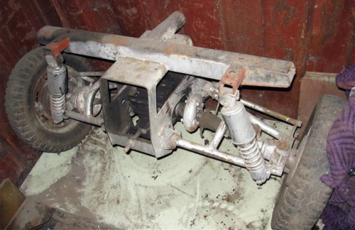
Scooter Ant is scooter truck with the body and the rear axle is designed to meet this (operation on country and rural roads, large weight loads). Rear Axle "Ant" includes a differential with the main transmission, suspension and drive the rear wheels.
Main gear increases the torque and passes it to the differential, and then the wheels. Torque is transmitted to the main transmission chain.
Consider how the rear axle assemblies in detail with images:
differential
differential housing (15) rotates together with the driven gear (22). To the body are tapered side gear (13) and the satellite gears (19). Each of the satellites is engaged with both gears. When driving on a flat road, satellites evenly distributes the power to the bevel gears, rotating on its axis. When reducing the speed of one of the wheels, and satellites begin to spin, increasing the speed of the other wheel.
Main gear scooter Ant.
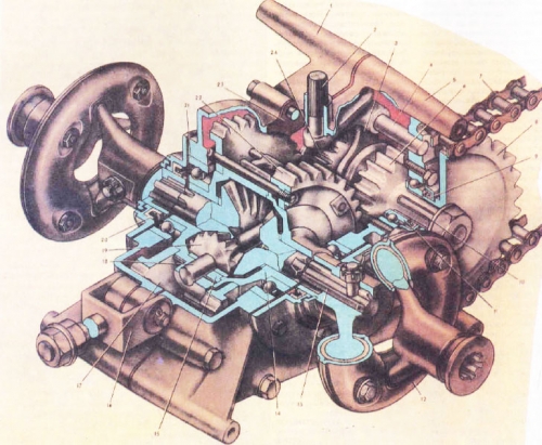
Fig. 1
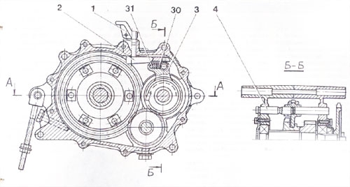
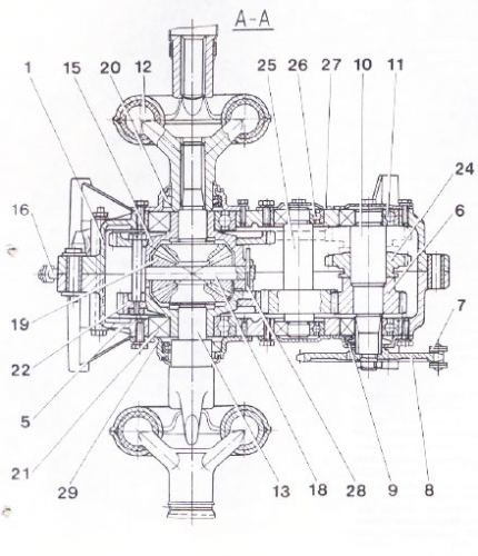
Fig. 2
Fig. 1-2:
- - crankcase main gear (the left half);
- - leash shift fork;
- - switching plug;
- - axis shift fork;
- - crankcase main gear (right half);
- - Forward drive gear;
- - chain;
- - asterisk;
- - gland;
- - drive shaft;
- - bearing 204;
- - metal universal joint;
- - axle differential;
- - the differential housing cover;
- - differential housing;
- - chain tensioner;
- - driven gear reverse;
- - axis of satellites;
- - gear-satellite;
- - gland;
- - bearing 207;
- - driven gear Forward;
- - laying;
- - reverse drive gear;
- - intermediate shaft;
- - bearing 203;
- - cover;
- - pin;
- - cover;
differentials combined in one unit with gear selection front and rear travel.
Main gear - gear m intermediate gear (27). Carter consists of 2 halves (1) and (5), which were cast in aluminum alloy AL-2. Driven sprocket drive (8) is mounted on the slots sticking out the end of the drive shaft (10) which rotates in bearings in the crankcase (11). On the shaft inside the crankcase freely available pinion gear (6), having a cam on the left side. On the slots available primary gear - clutch (24). Intermediate shaft with the gear (27) rotates on 2 bearings (26).
differential housing
differential housing (15) and cover (14) supported by the ball bearings (21), zapressovynnye in the crankcase. The cover (14) and the differential housing (15) tightened the bolts. The differentials are driven gears front (22) and rear (17) stroke. Inside the differential housing are still 2nd gear (13) and 2-a satellite (19).
satellites revolve on an axis (18), which is attached to a pin in the housing (15). At the ends of the gears (13), are the hinges (12) of rubber and metal, which are protected by chelas. The shaft (10), the torque is transmitted chain (7) and the driven sprocket (8).
When scooter is moving forward, cams gears (24) are in conjunction with cams pinion (6), which in turn passes the time on the driven gear (22) through the intermediate pinion shaft (27). When in reverse gear, the pinion (24) is engaged with the driven gear reverse (17).
Figure 3: Leading axis (16) transmits the rotation of the differential gear to the driven shafts. At the ends of the leading axis (16) mounted joints - Cardan. Propshaft is needed because when working spring rear suspension, wheels and half-close and removed from the body.
joints of metal and rubber are generally quite durable and require no maintenance. However, you need to follow the links coupling shells (17) bolts. Maximum allowable gap between the casing is 0.5 mm. Incisions rubber sleeve (14) in the locations of plugs leads and cuts in areas adjoining enclosures do not affect the joints.
When the drive shaft rotates (even at constant speed), the angular velocity of the driven shaft is changed 2 times in a turn (decreasing and increasing). This unevenness of rotation offset universal joints at both ends of the leading axis (otherwise it would cause a major effort on the driven shaft and the wheel bolts, which would lead to increased tire wear).
themselves rear wheels are driven by the following: Torque is transmitted from the differential leading pluosi (19) through a universal joint and spline connection. Axis (master and slave) connected to one another yet another rubber-metal universal joint (26). Wheel hub planted in Woodruff key (8) on the tapered end of the slave axis. Itself driven axle (1) rotates in 2 taper roller bearings (2), which are pressed into the steel sleeve of the balance.
Adjustment and lubrication of the rear suspension
to adjust both bearings, the inner ring of the bearing is moved to the outer driven shafts. You can make adjustments with the nuts (5) through the pressure ring. This operation is worth spending carefully, since in strong tight tightening the bearings get hot until melting and leaking grease and bearing failure. In addition, such a tight-tightening may cause the appearance of the "shells" on track rings in operation.
So to adjust the bearings, remove the wheel hub. Then, turning the driven axle, tighten the adjusting nut to tight rotation axis, then it is necessary to unscrew the nut 1-1,25 faces (if the bearings are already burnished) or 1.25-1.5 faces (if the bearings are new). After adjustment, the nut must Lock the (secure from unwinding). When'll attach the brake drum in place, make sure the Woodruff key (8) is set correctly - after assembly wheel should spin freely and do not have a significant gap.
After assembly, the first visits to check the heating hubs. Small heating is not oppasen. Heating, in which the hand is not "tolerate", should be removed by unscrewing the nut on the floor face. After a run of 200-300 km, it can turn the screw to its original state (on the floor garni).
When adjusting nut should not be delayed too weak, since the strong zatyazhenie easily seen (by heating the hub) and twist, but weak tightening define complex and thus may lead to a rapid failure of the bearings.
Kononicheskie bearings lubricated by filling the interior of the balancer hub grease (Lithol). Rubber gaskets (19) mounted on both sides of sleeve, do not give drain grease.
Rear Suspension
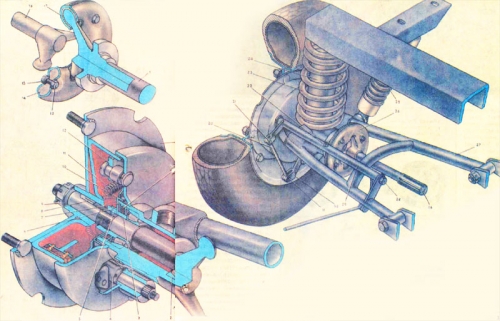
Fig. 3
rear suspension scooter truck "Ant" from the cradle to transfer vertical wheel load, and the wheels on the frame and push the brake force. The rear wheels have independent suspension (each wheel is connected to the frame with articulated arms that let you move up and down independently of the other wheels). This significantly reduces vibration suspension frame, especially when driving on uneven bumpy road.
suspension includes coil springs and counterweights. Lever (27) - welded pipes in the form of a trapezoid. One end of the structure is welded to a steel sleeve. The frame of a rocker pivotally fastened with sleeves welded to the other end of the design and pipes. The sleeve is welded to the body of the balance established pruzhzhina rear axle (23). The upper spring is mounted on the frame bracket. To protect it from contact turns and limit compression springs inside a rubber buffer (24). The oscillations are damped spring-hydraulic shock absorbers (25) mounted on a rocker.
Fig. 3. Suspension and rear wheel drive: 1 - slave axis 2 - 7205 roller bearing 3 - thrust ring, 4 - the cam brake, 5 - adjusting nut 6 - retaining 7 - Lock ring, 8 - key 9 - nut, 10 - cup, 11 - spring brake pads, 12 - brake shoe 13 - a bolt, 14 - rubber coupling, 15 - conical washer, 16 - Leading axle, 17 & mdash , coupling guard, 18 - rear hub, 19 - seal, 20 - brake rod small, 21 - axis, 22 - oiler, 23 - spring rear suspension, 24 - Rubber buffer, 25 - Shock Absorber spring applied, hydraulic, 26 - universal joint 27 - rocker, 28 - bolt-axis, 29 - brake pipe, 30 - brake lever cam, 31 - pin. |